
(AC-3) Output
by Eric Koester
last changed January 26, 2001
Click on pictures to see a larger image.
DISCLAIMER
This modification is to be done and there is no guarantee that the modification will
work for you. Failure to correctly install this design may result in damage
to you and/or your laserdisc player. This web site takes no responsibility
for any modification you may attempt.
HISTORY
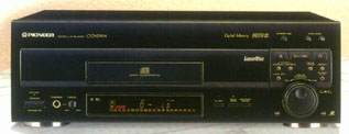
It was the summer of 1995 and I had just
purchased my Pioneer CLD-D703 laserdisc player.
In 1995, laserdisc players were the highest
quality of video and audio you could get for home theater. In 1995,
Dolby Pro Logic was still considered the state of the art in surround sound
formats. Only one year later, my player was
rendered obsolete by the next generation of laserdisc players that offered
the coveted Dolby AC-3 output - also called Dolby Digital by the marketing
department of Dolby Labs. According to
the Chronology of Dolby Laboratories
page, by September 1996, the 100th laser disc with 5.1-channel
AC-3 (Dolby Digital) audio, Twister, was already released. I had
just shelled out $850 for the D703 so that I could have all the cool bells
and whistles (like freeze and slow motion on CLV discs) and now I was already
missing out. Not only would I have to buy a new laserdisc player,
but a new receiver with a Dolby Digital decoder in it as well! I
was not ready for a complete system replacement. I decided to ignore
Dolby Digital as long as I could. Within months of the Dolby Digital
videodisc player introduction, DTS
started encoding their digital surround sound tracks onto laserdiscs.
With DTS, the D703 would work fine with no modification! That sounded
great! However, a new receiver with a DTS decoder in it would have
to be purchased...damn! There was still no way to win. There
was no way to economically have either Dolby Digital or DTS without buying
a new laserdisc player and/or a new receiver. I decided to wait some
more.
MY RESEARCH
One day in the fall of 1997, I was browsing
the internet for laserdisc sites and I came across a few laserdisc/AC-3
modification pages such as:
Kevin
Nakano's Do It Yourself AC-3 page
Pioneer
CLD-D703 Dolby Digital Modification page
Laserdiscs
and AC-3
After seeing these www pages, I realized
that I could relatively easily modify my laserdisc player myself and have
Dolby Digital output without buying a new laserdisc player! I had
no idea people were doing this. By the look of the pages, hundreds
of people around the world had done it! For a while, I considered
buying a mod kit from Precision
Laserdisc. In the fall of 1997, their upgrade kit was $75 plus $5 for
shipping.
Before I ordered one, I decided that I should open my laserdisc player
and see if I could predict how hard it was going to be to install the modification
board without their $80 worth of parts and instructions. I opened
up the player (now well out of warranty) and the audio board on the D703
was the very top board in the case! I didn't have to remove any boards
to get to the audio board. The points where I would have to attach
the coax cable and power wires were very obvious! All the points
I needed to find were clearly labeled on the pcb silk-screen! Cool!
I felt confident that I could save myself $80, make the board myself, figure
out where my connection points were and install it myself!
THE CIRCUIT
From what I have gathered, the circuit on
the modification board is a copy of the circuitry that Pioneer added to
models that came after the D703 to give them an RF Dolby Digital output.
I used circuit number 1 from Kevin
Nakano's www page.
CLICK
TO SEE CIRCUIT
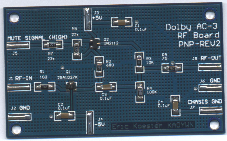
I layed out a small (1.5 inch x 3 inch) circuit
board using surface mount components and got the parts together for the
board.
| QUANTITY | DESCRIPTION |
| 1 | custom circuit board |
| 1 | Q1, switching PNP transistor SMT SOT-23 package - DigiKey # FMMT2907ACT-ND |
| 1 | Q2, general PNP transistor SMT SOT-23 package - DigiKey # FMMT3906CT-ND |
| 4 | 0.1uF capacitors SMT 1206 package - DigiKey # PCC104BCT-ND |
| 2 | 22k Ohm resistor SMT 1206 package - DigiKey # P22KECT-ND |
| 1 | 100 Ohm resistor SMT 1206 package - DigiKey # P100ECT-ND |
| 1 | 75 Ohm resistor SMT 1206 package - DigiKey # P75ECT-ND |
| 1 | 100k Ohm resistor SMT 1206 package - DigiKey # P100KECT-ND |
| 1 | 10k Ohm resistor SMT 1206 package - DigiKey # P10KECT-ND |
| 1 | 680 Ohm resistor SMT 1206 package - DigiKey # P680ECT-ND |
INSTALLATION
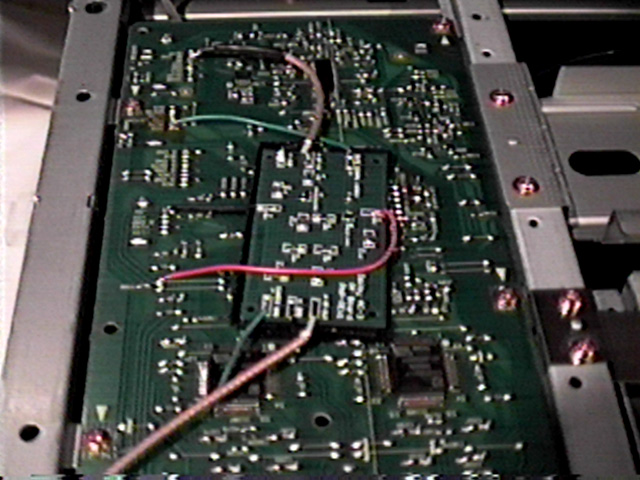
When you take the cover off the D703 and
look at the player with the player's back facing you, the audio board is
left-most horizontal pc board. The audio board measures roughly 5
inches wide by 15 inches tall.

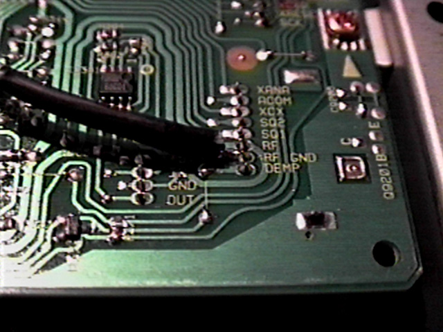
The RF signal (AFM signal) is labeled "RF"
in white printing on the pc board. To see the printing right-side-up,
you now need to rotate the player so you are looking at the front.
When looking at the audio board from the front of the player, the row of
pins that has the RF pin is in the lower right hand corner of the board.
The RF_GND pin is right next to it. I used 75 OHM mini coax for the
RF signal into the mod board and out of the RF board. I recommend
connecting the RF signal with coax since it is good engineering practice
to use it and I know this method works well. Those are the two pins
you will need to attach your coax cable that goes to the RF input of mod
board. The center conductor of the coax goes to the RF pin and the
shield of the coax goes to the GND pin.
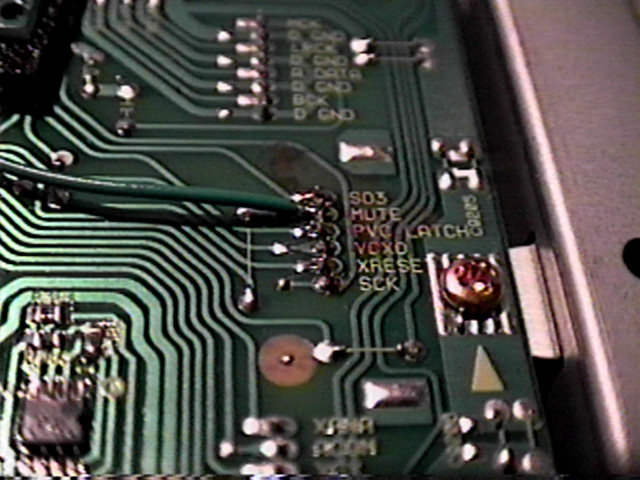
The next signal along the edge of the audio
board is the MUTE signal. I attached a wire from the MUTE pad on
the mod board and ran it to the pin labeled MUTE on the audio board.
It was about 2 inches away from the RF tap point.
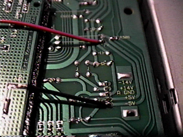
The next signals along the edge of the audio
board were the power pins. The mod board +5V and -5V. I found
them very clearly labeled about 3 inches away from the MUTE pin along the
edge of the board. The pins are right next to each other but I connected
the +5V wire to the +5V copper track (which connects to the +5V pin) a
little way away from the -5V pin just to make sure there wouldn't be any
chance of a short between +5V and -5V.
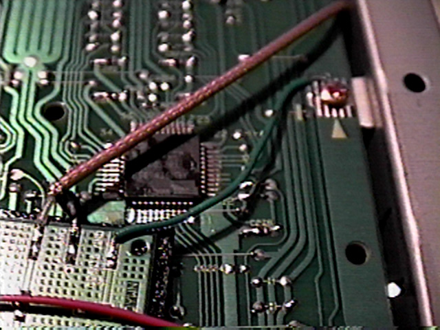
The next point along the edge of the audio
board that needs to be connected to the mod board is ground. There
are many points on the board that are labeled GND. I chose one of
the closest connection points to the mod board. I then soldered a
wire from the GND pad on the mod board to a pad that was electrically connected
to the audio board ground. It happened to be solder pads under one
of the chassis screws. In this picture, you can also see the RF output
coax running to the output RCA connector on the back panel of the player.
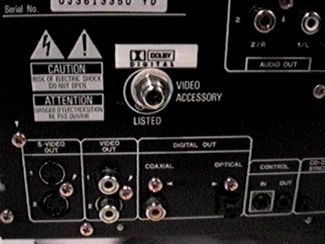
The RF output of the mod board is then connected
to the output RCA connector using 75 OHM mini coax. I tipped
the player up on it's side so that if metal particles from the drilling
fell, they would not lodge on any player circuit boards. The output
RCA connector should be insulated from the chassis of the laserdisc player
with spacers made of plastic or other insulating materials. I had
to remove the player's audio board in order to connect the coax to the
output RCA connector.
I ordered a set of RCA connectors and their
matching plastic washers from DigiKey. They were part numbers:
SC1134-ND RCA CONNECTOR
SC1146-ND INSULATED WASHER, FLAT
SC1147-ND INSULATED WASHER, EXTRUDED
After the output RCA connector had been installed
in the rear panel of the player and all the wires had been connected to
the mod board, it was time to secure the mod board in the player.
I chose to use Velcro to do this.
It was at this point that I got a laserdisc
to test the signal levels going in and out of the mod board during operation.
With the lid of the player still off, I plugged in the player's power cord
and loaded a laserdisc. I pressed play and probed the RF OUT pad
on the mod board with my oscilloscope probe. I watched the signal
on the scope as the disc played and as I hit the PAUSE button. The
RF signal was indeed riding on a dc level. The dc level of the signal
went to about +4.5V when the PAUSE button was hit and back to +2.5V when
the player was put back into PLAY mode. The levels matched the pictures
and values found on Kevin
Nakano's www page. All looked good. It was time to hook
the player's new AC-3 output to my AC-3 decoder.
The first AC-3 disc I tried was Star Trek: First Contact. I turned on the decoder and pressed play on the player. After the disc spun up to running speed, the AC-3 light on the decoder came on. The output of the speakers was drop dead silent and then sound emerged from the speakers! It worked! The first thing I noticed with AC-3 sound was how well separated the channels were! The dialog of the movie stayed in the center channel and did not bleed into the front right and front left channels as it does with Dolby Pro Logic Surround.
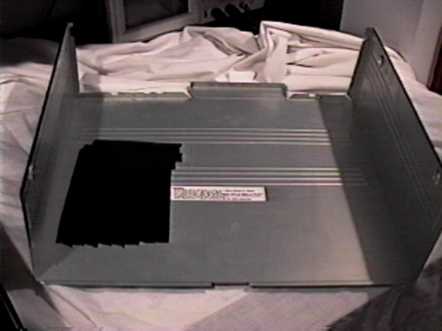
It was just about time to put the lid on
and finish the job. Since I installed the mod board with the wires
and components facing the inside surface of the player's metal lid, I decided
to put black electrical tape on the inside surface of the lid just to make
sure that the electrical connections on the mod board never touch the lid.
I then put the lid back on the player and
tried more laserdiscs. I was very pleased with the results of the
project.
I hope you found this page helpful and enlightening. My desire in putting this page up was to put forth the information that I learned and experience that I had with this project. By doing this, I hope to save other people some time in their journey to the AC-3 finish line!
If you have questions or comments, send an e-mail to
and I'll do my best to respond within a week.
BOARDS LEFT?
Nope, I sold them all.
LINKS TO OTHER AC-3 MODIFICATION
PAGES
Kevin
Nakano's Do It Yourself AC-3 page
Pioneer
CLD-D703 Dolby Digital Modification page
Laserdiscs
and AC-3
Laserdiscs
and AC-3 - Pioneer 2950 Specific Information
Samsung
LaserDisc Player DV500K modification
Modification
of a Pioneer CLD-1090
Modification
of a Pioneer CLD-A100
Pioneer
CLD-1450 Mods
DIY
Project # 3 - An AC-3 RF Output Upgrade
CLD-97
AC-3 RF Output Modification
Dolby
Digital (AC-3) Modifications for Laserdisc Players
Panasonic LX-900 AC-3 Upgrade Page
Modify the Pioneer CLD-S104 Laser Disc player for AC-3 RF output
MSB Technology
Precision
Laserdisc